Contact: Adjust to touch and Stabilization Damping
1. Introduction
1.1 Adjust to touch
- Adjust to touch is an option below Interface Treatment.
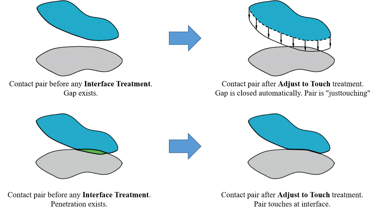
- The Interface Treatment property defines how the contact interface of a contact pair is treated. The property becomes visible when you set the contact Type property to either Frictionless, Rough or Frictional (nonlinear contact). For a given contact interface (Contact Region) that includes either gaps or penetrations, either locally or uniformly along the overall surface, contact adjustments, such as closing the gaps, removing the penetrations, or shifting the contact surface by an Offset may produce a better setup for initial contact.
- When active, the Interface Treatment property provides the options illustrated here. Each option is described below.

Any initial gaps are closed and any initial penetration is ignored creating an initial stress free state. Contact pairs are "just touching" as illustrated.
Note:
- The Adjust to Touch option does not lead to uniform contact between concentric cylinders that contain a small initial gap. For this situation, manually specify the gap as an offset in with the Add Offset, No Ramping option.
- Gaps may still be present if the contact pair has regions of differing gaps. When gaps exist, this setting makes sure that initial contact occurs by closing the smallest gap.
2.2. Stabilization Damping Factor
- A contact defined may initially have a near open status due to small gaps between the element meshes or between the integration points of the contact and target elements. The contact will not get detected during the analysis and can cause a rigid body motion of the bodies defined in the contact.
- The stabilization damping factor provides a certain resistance to damp the relative motion between the contacting surfaces and prevents rigid body motion. This contact damping factor is applied in the contact normal direction and it is valid only for the Frictionless, Rough, and Frictional options of the Type property. The damping is applied to each load step where the contact status is open.
- The value of the stabilization damping factor should be large enough to prevent rigid body motion but small enough to ensure a solution. A value of 1 is usually appropriate. Property options are described below.
- 0 (default value), damping is activated for the first load step only. The solver uses a default value of 1.0 as the Stabilization Damping Factor.
- Non-zero, then damping is always activated regardless of the contact status of the previous substeps. The solver uses to apply stabilization damping.
- The Contact Stabilization Damping does not have a physical basic and is only a numerical technique used to achieve convergence -> Energy contributed by Contact Stabilization is an artificial energy and should be kept to a minimum.
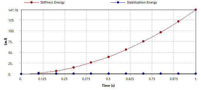
- After solving, it’s important to check the Stabilization Energy and ensure that it’s a small percentage of strain energy
Estabilization << Estrain
- If the contact stabilization energy is much less than the potential energy (for example, within a 1.0 percent tolerance), the results should be acceptable.
- Stabilization Energy and Stiffness Energy measurement methods:
- Method 1 (must insert before solving): RMB on Solution Information branch
- > Insert > Stiffness Energy (strain energy)
- > Insert > Contact > Type = Stabilization Energy
- Method 1 (must insert before solving): RMB on Solution Information branch

- Method 2: Use APDL commands
- RMB on Solution branch > Insert > Command Object

2. Example
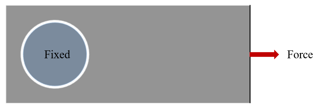
Consider a 2D Plane Stress analysis of pin and plate assembly as picture.
- A gap between the pin and the plate is 0.5mm
- The pin is fixed. A force applied on right side of the plate
Solve the problem in 3 cases:
- Use default contact settings
- Use Adjust to Touch contact
- Use Stabilization Damping
2.1. Case 1: use default contact settings
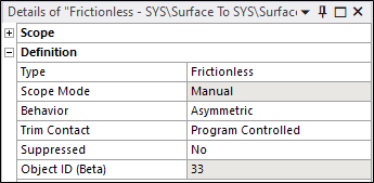
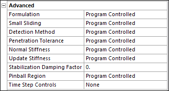
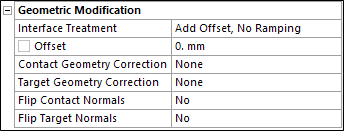
The solution fails after few iterations:
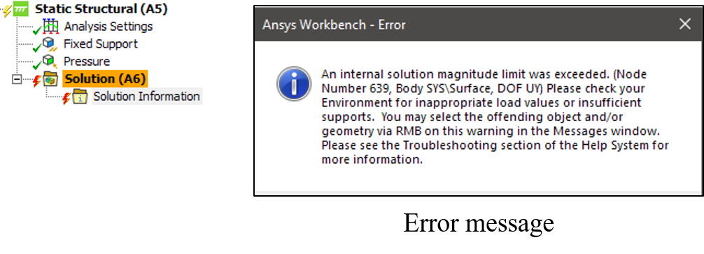
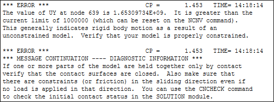
2.2. Case 2: Use Adjust to Touch contact
- The solution converges in a few iterations
- Review results: Total Deformation and Equivalent Stress

- Although the Adjust to Touch option resolves the convergence issue, it fails to accurately represent the gap between the pin and the plate: it has introduced a rigid region around the perimeter of the pin, and thus the gap is effectively being ignored.
2.3. Case 3: Use Stabilization Damping
- Stabilization Damping Factor = 5e-4
- Insert Stiffness Energy and Stabilization Energy below Solution Information branch to check artificial energy
- Review results: Total Deformation and Equivalent Stress

- Check the Artificial Energy and Stiffness Energy
- Artificial Energy = 0.426 mJ
- Stiffness Energy = 147.78 mJ
- Tolerance = 0.29% --> Acceptable
